Relay Module Types and Wiring
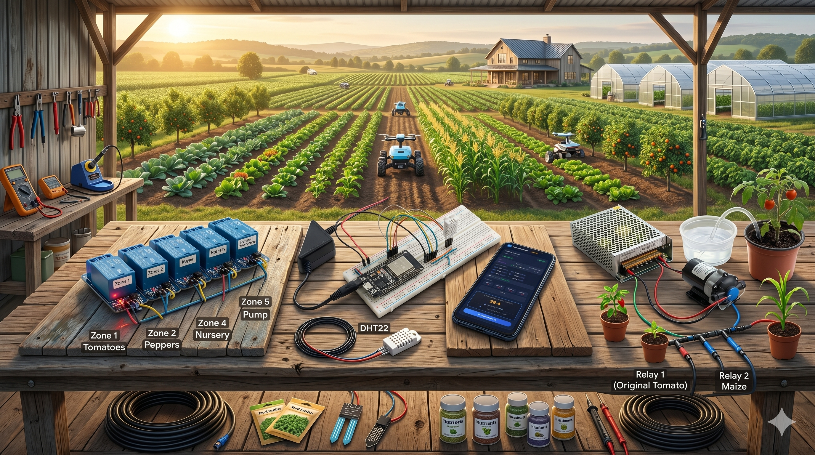
🔌 Relay Module Types and Wiring - Complete Guide for IoT Automation
⚡ What You'll Learn in This Lesson:
- 🔌 Understand different relay types (1, 2, 4, 8, 16-channel)
- ⚡ Learn proper wiring to ESP32/ESP8266 (5V vs 3.3V logic)
- 🛡️ Master optocoupler isolation for ESP protection
- 💧 Control water pumps, lights, and motors safely
- 🔧 Build multi-zone irrigation systems with relays
📊 What is a Relay and Why Do You Need One?
Your ESP32 outputs 3.3V at 40mA max - not enough to run a water pump (12V/2A) or a light bulb (220V/1A)! A relay sits between your ESP32 and the high-power device, acting as a bridge.
🔧 How a Relay Works: When the ESP32 sends a LOW or HIGH signal to the relay module, an internal electromagnet activates, physically closing or opening the high-power circuit. It's like a remote-controlled light switch!
📊 Relay Types Comparison
| Type | Channels | Voltage | Current Rating | Optocoupler | Best For |
|---|---|---|---|---|---|
| 1-Channel Relay | 1 | 5V / 12V / 24V | 10A / 250V AC | Optional | Single pump, single light |
| 2-Channel Relay | 2 | 5V | 10A / 250V AC | ✅ Yes | 2 zone irrigation |
| 4-Channel Relay | 4 | 5V | 10A / 250V AC | ✅ Yes | 4 zone irrigation, home automation |
| 8-Channel Relay | 8 | 5V | 10A / 250V AC | ✅ Yes | Greenhouse control, industrial automation |
| 16-Channel Relay | 16 | 5V | 10A / 250V AC | ✅ Yes | Large farm automation [citation:1] |
Start with a 4-channel 5V relay module with optocoupler isolation ($6-8 on AliExpress/Amazon). This gives you 4 zones (e.g., tomatoes, peppers, maize, nursery) and protects your ESP32 from electrical spikes from pumps [citation:1].
🔌 Understanding Relay Module Pins
🔴 Low-Voltage Side (ESP32 Side)
- VCC: 5V power from ESP32 VIN pin (or external supply)
- GND: Common ground with ESP32
- IN1, IN2, IN3, IN4: Control pins from ESP32 GPIO [citation:4]
⚡ High-Voltage Side (Load Side)
- COM (Common): Main power input (e.g., 12V for pump)
- NO (Normally Open): Circuit OPEN when relay OFF
- NC (Normally Closed): Circuit CLOSED when relay OFF [citation:8]
🛡️ JD-VCC Jumper (Optocoupler)
- Jumper ON: Relay powered from ESP32 (simple) [citation:10]
- Jumper OFF: Use external power for relays (safer!) [citation:10]
- Remove jumper = physical isolation from ESP32!
Most 5V relay modules are ACTIVE LOW - meaning digitalWrite(pin, LOW) turns the relay ON, and digitalWrite(pin, HIGH) turns it OFF. Test your relay with a simple sketch first!
🔌 Complete Relay Wiring to ESP32
═══════════════════════════════════════════════════════════════════════════════
                 4-CHANNEL RELAY MODULE WIRING TO ESP32
═══════════════════════════════════════════════════════════════════════════════

    Relay Module (4-Channel)              ESP32 Development Board
    ════════════════════════              ══════════════════════

    VCC (5V)                 ─────────►  VIN (5V pin)
    GND                      ─────────►  GND
    IN1 (Relay 1)            ─────────►  GPIO5
    IN2 (Relay 2)            ─────────►  GPIO18
    IN3 (Relay 3)            ─────────►  GPIO19
    IN4 (Relay 4)            ─────────►  GPIO21 [citation:4]

    JD-VCC Jumper: REMOVE for external power (SAFER!)

    ┌─────────────────────────────────────────────────────────────────────────┐
    │                         External Power (Recommended)                     │
    │                                                                          │
    │   External 5V/2A ──► JD-VCC (Relay Module)                             │
    │   Power Supply    ──► GND (Relay Module) - SHARED with ESP32 GND!      │
    └─────────────────────────────────────────────────────────────────────────┘

═══════════════════════════════════════════════════════════════════════════════
                CONNECTING A WATER PUMP (12V) TO THE RELAY
═══════════════════════════════════════════════════════════════════════════════

    Relay Module                          Water Pump (12V)
    ════════════════                      ═════════════════

    COM (Common)            ─────────►  +12V from power supply
    NO (Normally Open)      ─────────►  Pump Positive (+)
    Pump Negative (-)       ─────────►  12V Power Supply GND

    ⚠️ CRITICAL: Add a flyback diode (1N4007) across pump terminals!
    Diode band (cathode) facing POSITIVE terminal.
    This protects the relay from voltage spikes when pump turns OFF [citation:1].

═══════════════════════════════════════════════════════════════════════════════
🛡️ Optocoupler Isolation - Why It's Important
🌟 What is Optocoupler Isolation?
An optocoupler uses light to transmit signals between the ESP32 and the relay. There is NO electrical connection between the two sides - only light! This means electrical spikes from your pump CANNOT damage your ESP32 [citation:6].
| Configuration | Jumper Setting | ESP32 Protection | When to Use |
|---|---|---|---|
| Non-Isolated (Simple) | Jumper ON | ❌ NO protection | Low-power devices (LEDs, fans) |
| Isolated (Recommended) | Jumper OFF + External 5V | ✅ FULL protection | Water pumps, motors, AC devices [citation:10] |
🔧 Complete Arduino Code for Relay Control
/*
 * 4-Channel Relay Control for Smart Irrigation
 * Controls water pumps, lights, or any high-power device
 *
 * Components:
 * - ESP32 board
 * - 4-Channel 5V Relay Module (with optocoupler)
 * - 4x Water pumps or valves
 * - 12V/24V power supply for pumps
 */

// ========== PIN DEFINITIONS ==========
#define RELAY_ZONE1 5    // GPIO5 - Zone 1 (Tomatoes)
#define RELAY_ZONE2 18   // GPIO18 - Zone 2 (Peppers)
#define RELAY_ZONE3 19   // GPIO19 - Zone 3 (Corn)
#define RELAY_ZONE4 21   // GPIO21 - Zone 4 (Nursery)

// ========== IRRIGATION SCHEDULE (seconds) ==========
const int WATER_DURATION = 600;  // 10 minutes per zone
const int DELAY_BETWEEN_ZONES = 5000;  // 5 seconds pause

void setup() {
    Serial.begin(115200);

    // Set relay pins as OUTPUT
    pinMode(RELAY_ZONE1, OUTPUT);
    pinMode(RELAY_ZONE2, OUTPUT);
    pinMode(RELAY_ZONE3, OUTPUT);
    pinMode(RELAY_ZONE4, OUTPUT);

    // IMPORTANT: Most 5V relays are ACTIVE LOW!
    // HIGH = Relay OFF, LOW = Relay ON
    digitalWrite(RELAY_ZONE1, HIGH);
    digitalWrite(RELAY_ZONE2, HIGH);
    digitalWrite(RELAY_ZONE3, HIGH);
    digitalWrite(RELAY_ZONE4, HIGH);

    Serial.println("═══════════════════════════════════════════");
    Serial.println("💧 SMART IRRIGATION SYSTEM v1.0");
    Serial.println("   4-Zone Relay Control");
    Serial.println("═══════════════════════════════════════════");
    Serial.println("⚠️ Relays are ACTIVE LOW");
    Serial.println("   LOW = Pump ON  |  HIGH = Pump OFF\n");
}

// ========== CONTROL INDIVIDUAL ZONE ==========
void waterZone(int relayPin, const char* zoneName, int durationSeconds) {
    Serial.printf("💧 Zone %s: Watering for %d seconds\n", zoneName, durationSeconds);

    // Turn pump ON (ACTIVE LOW)
    digitalWrite(relayPin, LOW);
    delay(durationSeconds * 1000);

    // Turn pump OFF
    digitalWrite(relayPin, HIGH);
    Serial.printf("✅ Zone %s: Complete\n\n", zoneName);
}

// ========== WATER ALL ZONES IN SEQUENCE ==========
void waterAllZones() {
    Serial.println("━━━━━━━━━━━━━━━━━━━━━━━━━━━━━━━━━━━━━━━━━━━━━");
    Serial.println("🌾 STARTING SEQUENTIAL IRRIGATION");
    Serial.println("━━━━━━━━━━━━━━━━━━━━━━━━━━━━━━━━━━━━━━━━━━━━━\n");

    waterZone(RELAY_ZONE1, "Tomatoes", WATER_DURATION);
    delay(DELAY_BETWEEN_ZONES);

    waterZone(RELAY_ZONE2, "Peppers", WATER_DURATION);
    delay(DELAY_BETWEEN_ZONES);

    waterZone(RELAY_ZONE3, "Corn", WATER_DURATION);
    delay(DELAY_BETWEEN_ZONES);

    waterZone(RELAY_ZONE4, "Nursery", WATER_DURATION);

    Serial.println("━━━━━━━━━━━━━━━━━━━━━━━━━━━━━━━━━━━━━━━━━━━━━");
    Serial.println("✅ ALL ZONES COMPLETE");
    Serial.println("━━━━━━━━━━━━━━━━━━━━━━━━━━━━━━━━━━━━━━━━━━━━━\n");
}

// ========== CONTROL INDIVIDUAL ZONE (Manual) ==========
void setZone(int zoneNumber, bool turnOn) {
    int relayPin;
    const char* zoneName;

    switch(zoneNumber) {
        case 1: relayPin = RELAY_ZONE1; zoneName = "Tomatoes"; break;
        case 2: relayPin = RELAY_ZONE2; zoneName = "Peppers"; break;
        case 3: relayPin = RELAY_ZONE3; zoneName = "Corn"; break;
        case 4: relayPin = RELAY_ZONE4; zoneName = "Nursery"; break;
        default: return;
    }

    if (turnOn) {
        digitalWrite(relayPin, LOW);
        Serial.printf("✅ Zone %s: PUMP ON\n", zoneName);
    } else {
        digitalWrite(relayPin, HIGH);
        Serial.printf("✅ Zone %s: PUMP OFF\n", zoneName);
    }
}

void loop() {
    // Example 1: Water all zones in sequence (for daily irrigation)
    waterAllZones();

    // Wait 6 hours before next cycle
    Serial.println("⏰ Waiting 6 hours until next irrigation cycle...\n");
    delay(21600000);  // 6 hours = 21,600,000 ms

    // Example 2: Individual zone control (uncomment to use)
    /*
    setZone(1, true);   // Turn ON Tomatoes zone
    delay(600000);      // Water for 10 minutes
    setZone(1, false);  // Turn OFF Tomatoes zone
    delay(1000);
    */
}
🔧 Testing Your Relay - Determine Active LOW or HIGH
/*
 * Relay Test Sketch - Determine if your relay is Active LOW or Active HIGH
 *
 * Run this sketch and listen for the "click" sound
 */

#define RELAY_PIN 5

void setup() {
    Serial.begin(115200);
    pinMode(RELAY_PIN, OUTPUT);

    Serial.println("Testing Relay - Listen for click");
    Serial.println("════════════════════════════════════");

    // Test Active LOW
    Serial.println("Test 1: Setting pin LOW...");
    digitalWrite(RELAY_PIN, LOW);
    delay(2000);

    Serial.println("Test 2: Setting pin HIGH...");
    digitalWrite(RELAY_PIN, HIGH);
    delay(2000);

    Serial.println("\n✅ If relay clicked when LOW → Active LOW relay");
    Serial.println("✅ If relay clicked when HIGH → Active HIGH relay");
}

void loop() {
    // Nothing here
}
A small farm in Kiambu, Kenya installed a 4-channel relay system connected to an ESP32:
- 💧 Setup: 4 zones (Tomatoes, Peppers, Maize, Nursery)
- 💧 Components: ESP32 + 4-channel 5V relay + 4 DC pumps (12V)
- 💡 Challenge: Initial relays died after 2 weeks (no flyback diodes!)
- ✅ Fix: Added 1N4007 diodes across each pump - relays lasted 2+ years [citation:1]
- 💧 Result: Reduced manual watering labor by 15 hours/week
"The flyback diodes saved our system. Without them, we would have burned through relays every month!" - Farm Owner, Kiambu
⚡ Power Supply Requirements for 5V Relays
| Relay Channels | Coil Current per Relay | Total Current (All ON) | Required Power Supply |
|---|---|---|---|
| 1-Channel | ~70mA | 70mA | 5V/500mA (ESP32 USB is fine) |
| 2-Channel | ~70mA each | 140mA | 5V/1A (ESP32 USB might be borderline) |
| 4-Channel | ~70mA each | 280mA | 5V/2A (Use external supply!) |
| 8-Channel | ~70mA each | 560mA | 5V/3A (External power MANDATORY) [citation:1] |
| 16-Channel | ~70mA each | 1120mA (1.1A) | 5V/5A (External power + heavy wiring) [citation:1] |
The ESP32's voltage regulator can only supply ~500mA total. For 4+ relays, use an external 5V power supply (2A or higher) to power the relay module. Connect the external supply's GND to ESP32 GND [citation:10].
📋 Quick Reference - Relay Troubleshooting
| Problem | Likely Cause | Solution |
|---|---|---|
| ❌ Relay doesn't click | Wrong voltage or wiring | Check VCC (5V) and GND connections |
| ❌ Relay clicks but pump doesn't run | High-voltage wiring wrong | Check COM and NO connections (not NC!) |
| ❌ Relay works but ESP32 resets | Power supply insufficient | Use external 5V/2A for relays [citation:10] |
| ❌ Pump/light stays on always | Relay contacts welded | Add flyback diode (pump) or replace relay |
You can now safely control high-power devices with your ESP32!
- ✅ Choose the right relay module for your farm (1, 2, 4, 8, 16 channels)
- ✅ Wire relays correctly to ESP32 (5V, GND, GPIO pins)
- ✅ Use optocoupler isolation to protect ESP32 from electrical spikes
- ✅ Add flyback diodes to pumps and motors [citation:1]
- ✅ Build multi-zone automated irrigation systems
Next step: Add soil moisture sensors to automate irrigation based on soil conditions!
┌─────────────────────────────────────────────────────────────────────────────┐
│                    RELAY MODULE BUYING GUIDE                                │
├─────────────────────────────────────────────────────────────────────────────┤
│                                                                             │
│  ✅ LOOK FOR:                                                               │
│     • 5V coil voltage (compatible with ESP32)                              │
│     • Optocoupler isolation (EL817 or similar)                             │
│     • JD-VCC jumper (for external power option)                            │
│     • Contact rating ≥10A at 250V AC                                       │
│                                                                             │
│  ❌ AVOID:                                                                  │
│     • Relays without optocoupler (cheap blue boards)                       │
│     • 3.3V relays (ESP32 can drive them but less common)                   │
│     • "Songle" relays without specifications                               │
│                                                                             │
│  💰 PRICE RANGE (2025):                                                    │
│     • 1-Channel: $2-3 (AliExpress) / $5-7 (Amazon)                        │
│     • 4-Channel: $5-7 (AliExpress) / $10-12 (Amazon)                      │
│     • 8-Channel: $12-15 (AliExpress) / $20-25 (Amazon) [citation:6]       │
│     • 16-Channel: $25-30 (AliExpress) / $40-50 (Amazon) [citation:1]      │
│                                                                             │
└─────────────────────────────────────────────────────────────────────────────┘
- Apply these concepts directly to your farm or project.
- Take notes on important details for the quiz.
- Use the button below to track your progress.