← Back to Course
Pico W Pinout and Wiring Guide
🔌 Raspberry Pi Pico W Pinout Guide - Complete Reference
🔌 What You'll Learn:
- 📊 Understand all 40 pins on the Pico W
- 🔧 Know which pins are for GPIO, ADC, PWM, I2C, SPI, UART
- ⚡ Learn power pin limitations (3.3V = 300mA max)
- ⚠️ Avoid common wiring mistakes (3.3V logic only!)
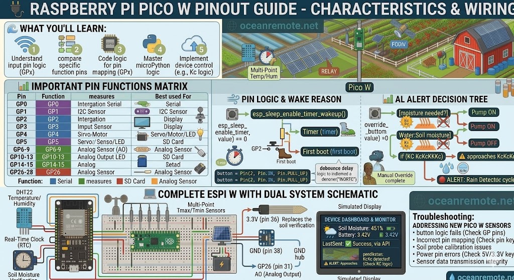
📊 Important Pin Functions
- GP0, GP1: UART0 - Serial communication (TX/RX)
- GP2, GP3: I2C1 (SDA/SCL) - I2C sensors (BME280, etc.)
- GP4, GP5: SPI0 - SPI devices, displays
- GP6-GP9: PWM - Servo control, LED dimming
- GP10-GP13: SPI1 - SD cards, additional SPI sensors
- GP14-GP15: PWM - Motor control, LEDs, buzzers
- GP26-GP28: ADC pins - Analog sensors (soil moisture, light, pH) - ONLY these 3!
- GP22: Onboard LED (built-in LED control)
- GP23, GP24, GP25: Used by WiFi - avoid using these
💡 ADC Pins are LIMITED!
Only GP26, GP27, GP28 can read analog signals (0-3.3V → 0-65535). All other GPIO are digital only (0 or 1). For multiple analog sensors, use these 3 pins or add an external ADC.
🔌 Power Pins
- 3.3V (pin 36): Output for sensors (max 300mA total)
- 5V (pin 40): Input from USB or external 5V power supply
- VSYS (pin 39): 1.8-5.5V input for battery operation
- GND: Multiple ground pins available (pins 3, 8, 13, 18, 23, 28, 33, 38)
- RUN (pin 36): Reset pin - pull low to reset
⚠️ CRITICAL WARNINGS:
- 3.3V LOGIC ONLY: Pico W uses 3.3V - NEVER connect 5V to GPIO pins!
- ADC pins are GP26, GP27, GP28 ONLY (pins 31, 32, 34)
- GP23, GP24, GP25 are used by WiFi - avoid using them
- 3.3V pin max current: 300mA total (sensors + onboard)
- VSYS range: 1.8-5.5V (can use single 18650 battery directly!)
🔌 Common Sensor Wiring Examples
Soil Moisture Sensor (Analog)
Pico W           →  Soil Moisture Sensor
3.3V (pin 36)    →  VCC
GND (pin 38)     →  GND
GP26 (pin 31)    →  AO (Analog Output)
DHT22 (Digital)
Pico W           →  DHT22
3.3V (pin 36)    →  VCC
GND (pin 38)     →  GND
GP0 (pin 1)      →  DATA (with 10kΩ pull-up to 3.3V)
Relay Module (Digital Output)
Pico W           →  Relay Module
3.3V (pin 36)    →  VCC
GND (pin 38)     →  GND
GP1 (pin 2)      →  IN (Control pin)
I2C Sensor (BME280)
Pico W           →  BME280
3.3V (pin 36)    →  VCC
GND (pin 38)     →  GND
GP2 (pin 4)      →  SDA
GP3 (pin 5)      →  SCL
💡 Quick Reference - Best Pins For:
- Analog sensors (soil, light, pH): GP26, GP27, GP28 (ONLY these!)
- I2C Devices (BME280, OLED): GP2 (SDA), GP3 (SCL)
- UART/Serial (GPS, debugging): GP0 (TX), GP1 (RX)
- Simple buttons/LEDs: Any free GPIO except GP23-25
- Relays/Pumps: Any free GPIO (use external 5V power)
🎯 Key Takeaways:
- ✅ 40 total pins: 26 GPIO, 3 ADC, 8 GND, power pins
- ✅ ADC pins: GP26, GP27, GP28 only (pins 31, 32, 34)
- ✅ 3.3V output max 300mA - enough for 2-3 sensors
- ✅ VSYS (pin 39) accepts 1.8-5.5V - perfect for 18650 battery
- ✅ Avoid GP23, GP24, GP25 (reserved for WiFi)
💡 Key Takeaways:
- Apply these concepts directly to your farm or project.
- Take notes on important details for the quiz.
- Use the button below to track your progress.
×
![Enlarged view]()