← Back to Course
ESP8266 Pinout and Wiring Guide
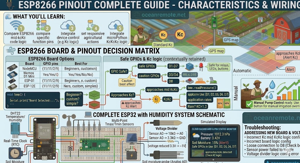
🔌 ESP8266 Pinout Complete Guide - NodeMCU, Wemos D1 Mini, ESP-01
🔌 What You'll Learn:
- 📊 Compare popular ESP8266 boards: NodeMCU, Wemos D1 Mini, ESP-01
- ✅ Know which GPIO pins are safe to use (and which to avoid)
- 🔧 Understand boot behavior (some pins affect startup)
- ⚠️ Learn the critical ADC limitation (0-1V only!)
📊 Popular ESP8266 Boards
- NodeMCU ($6-8): 11 GPIO pins, USB port, voltage regulator. Best for beginners and prototyping.
- Wemos D1 Mini ($4-6): 11 GPIO pins, USB port, very compact. Great for compact projects.
- ESP-01 ($2-3): Only 2 GPIO pins, NO USB (needs adapter). For simple sensors, size-constrained.
- ESP-12E ($3-5): 9 GPIO pins, NO USB. For custom PCB design.
💡 Recommendation for Beginners:
Buy a NodeMCU or Wemos D1 Mini. They have USB ports, built-in voltage regulators, and clearly labeled pins. ESP-01 modules require extra hardware (adapter, 3.3V regulator) and are frustrating for beginners.
✅ Safe GPIO Pins for NodeMCU / Wemos D1 Mini
- D1 (GPIO5), D2 (GPIO4): ✅ Completely safe - perfect for relays, LEDs, buttons
- D5 (GPIO14), D6 (GPIO12), D7 (GPIO13): ✅ Safe general purpose pins
- D3 (GPIO0), D4 (GPIO2): ⚠️ Use with caution - affect boot (must be HIGH at boot)
- D8 (GPIO15): ⚠️ Must be LOW at boot (add pull-down resistor)
- D9 (GPIO3/RX), D10 (GPIO1/TX): ⚠️ Serial pins - avoid if using USB
- D0 (GPIO16): ⚠️ Digital only, no pull-up, can wake from deep sleep
⚠️ Boot Behavior - Critical to Know:
- GPIO0 LOW at boot: Enters flashing mode (won't run your code)
- GPIO2 LOW at boot: Affects boot, may fail
- GPIO15 HIGH at boot: Boot failure
- Rule: GPIO0, GPIO2 should be HIGH at boot. GPIO15 should be LOW at boot.
- Safe pins for buttons: GPIO4, GPIO5, GPIO14, GPIO12, GPIO13
🔌 Basic Wiring Examples
Soil Moisture Sensor (with voltage divider)
NodeMCU ESP8266        →  Soil Moisture Sensor
3.3V                  →  VCC
GND                   →  GND
A0                    →  AO (with voltage divider - see below!)

⚠️ ESP8266 ADC only accepts 0-1V! Use voltage divider:
Sensor AO ──┬── 10kΩ resistor ──┬── A0
            │                   │
            └── 5.6kΩ resistor ──┴── GND
Relay Control (Safe pin: D1/GPIO5)
NodeMCU           →  Relay Module
3.3V             →  VCC
GND              →  GND
GPIO5 (D1)       →  IN
DHT22 (with pull-up)
NodeMCU           →  DHT22
3.3V             →  VCC
GND              →  GND
GPIO4 (D2)       →  DATA (with 10kΩ pull-up to 3.3V)
💡 Quick Reference - Best Pins For:
- Analog sensors (soil moisture, light): A0 ONLY (with voltage divider!)
- Relays / pumps: GPIO4, GPIO5, GPIO14 (D2, D1, D5)
- Buttons (input): GPIO4, GPIO5, GPIO14 (with INPUT_PULLUP)
- LEDs (output): GPIO4, GPIO5, GPIO14, GPIO12, GPIO13
- I2C sensors: GPIO4 (SDA), GPIO5 (SCL) or GPIO14 (SDA), GPIO12 (SCL)
🎯 Key Takeaways:
- ✅ NodeMCU or Wemos D1 Mini are best for beginners
- ✅ Safe pins: GPIO4, GPIO5, GPIO12, GPIO13, GPIO14
- ✅ Avoid GPIO0, GPIO2, GPIO15 for buttons/switches (boot issues)
- ✅ A0 is the ONLY analog pin (0-1V only - use voltage divider!)
- ✅ All GPIO are 3.3V logic - never connect 5V directly
💡 Key Takeaways:
- Apply these concepts directly to your farm or project.
- Take notes on important details for the quiz.
- Use the button below to track your progress.
×
![Enlarged view]()