← Back to Course
Digital Output: Controlling LEDs and Relays
💡 Digital Output: Controlling LEDs and Relays with ESP32
💡 What You'll Learn:
- 🔌 Control LEDs, buzzers, and relays using digital output
- 💧 Automate water pumps based on soil moisture readings
- ⚡ Understand HIGH (3.3V) vs LOW (0V) signals
- 🌾 Save 30-40% of water with automated irrigation
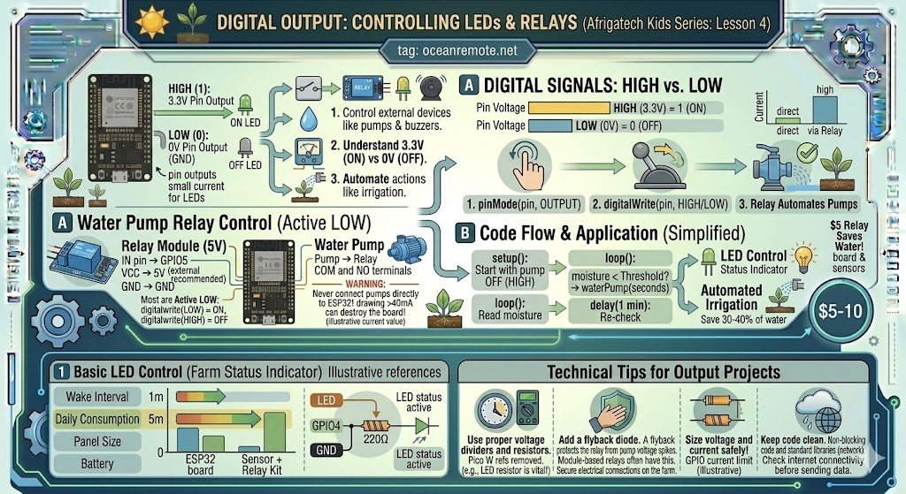
Digital output allows you to control external devices like LEDs, buzzers, and relays. This is how you'll control water pumps, lights, and alarms in your IoT projects. A relay can switch pumps on/off automatically - no manual intervention needed!
🔧 How Digital Output Works
- HIGH (1): Pin outputs 3.3V (enough to power a small LED)
- LOW (0): Pin outputs 0V (GND - completes the circuit)
- Use
pinMode(pin, OUTPUT)to set pin as output - Use
digitalWrite(pin, HIGH/LOW)to set the value - ⚠️ Never connect pumps directly to ESP32! Always use a relay module.
📊 Pin Reference for Digital Output
| Device | Recommended GPIO | Notes |
|---|---|---|
| LED | GPIO4, GPIO5, GPIO16, GPIO17 | Always use 220Ω resistor in series |
| Relay (Pump) | GPIO5, GPIO18, GPIO19, GPIO21 | Use external 5V power for relay module |
| Buzzer | GPIO13, GPIO14, GPIO27 | Passive buzzer needs PWM for tones |
| Servo Motor | GPIO13, GPIO14, GPIO15 | Requires PWM library |
| Fan/DC Motor | GPIO5, GPIO18, GPIO19 | Always use relay or motor driver |
💡 Understanding Digital Signals:
Digital output is either ON (HIGH/3.3V) or OFF (LOW/0V). It's like a light switch - no in-between. For dimming LEDs or controlling motor speed, you'll need PWM (covered in another lesson). For simple ON/OFF control of pumps, digital output is perfect!
💡 Basic LED Control Example
/*
 * LED Control - Farm Status Indicator
 * Connect LED anode (long leg) → 220Ω resistor → GPIO4
 * Connect LED cathode (short leg) → GND
 */

#define LED_PIN 4

void setup() {
    pinMode(LED_PIN, OUTPUT);
    Serial.begin(115200);
    Serial.println("🌱 Farm Status LED Ready");
}

void loop() {
    // Blink pattern: ON for 1 second, OFF for 1 second
    digitalWrite(LED_PIN, HIGH);
    Serial.println("🔴 LED ON - System active");
    delay(1000);

    digitalWrite(LED_PIN, LOW);
    Serial.println("⚫ LED OFF");
    delay(1000);
}
💧 Water Pump Relay Control (Active LOW)
/*
 * Automatic Water Pump Control with Relay
 * Connect relay IN pin → GPIO5
 * Connect relay VCC → 3.3V, GND → GND
 * Water pump connects to relay COM and NO terminals
 *
 * ⚠️ Most 5V relays are ACTIVE LOW:
 * - digitalWrite(LOW) = Pump ON
 * - digitalWrite(HIGH) = Pump OFF
 */

#define RELAY_PIN 5
#define SOIL_MOISTURE_THRESHOLD 30

void setup() {
    pinMode(RELAY_PIN, OUTPUT);
    digitalWrite(RELAY_PIN, HIGH);  // Start with pump OFF
    Serial.begin(115200);
    Serial.println("💧 Smart Irrigation System Started");
}

void waterPump(int seconds) {
    Serial.printf("💧 Watering for %d seconds...\n", seconds);
    digitalWrite(RELAY_PIN, LOW);   // Turn pump ON
    delay(seconds * 1000);
    digitalWrite(RELAY_PIN, HIGH);  // Turn pump OFF
    Serial.println("✅ Watering complete");
}

void loop() {
    // Read soil moisture (replace with actual sensor reading)
    int soilMoisture = analogRead(32);
    int moisturePercent = map(soilMoisture, 3800, 1500, 0, 100);
    moisturePercent = constrain(moisturePercent, 0, 100);

    Serial.printf("💧 Soil moisture: %d%%\n", moisturePercent);

    if (moisturePercent < SOIL_MOISTURE_THRESHOLD) {
        Serial.println("⚠️ Soil too dry! Starting irrigation...");
        waterPump(10);  // Water for 10 seconds
    } else {
        Serial.println("✅ Soil moisture adequate - No watering needed");
    }

    delay(60000);  // Check every minute
}
⚠️ Important Safety Notes:
- Never connect pumps directly to ESP32 - they draw too much current (will destroy the board)
- Always use a relay module rated for your pump's voltage and current
- Add a flyback diode across pump terminals to protect the relay from voltage spikes
- Test your relay to determine if it's active LOW or active HIGH
💧 Real Application:
An automated irrigation system using a relay can save 30-40% of water by watering only when soil moisture drops below threshold. A $5 relay can save hundreds of dollars in water costs annually!
🎯 Quick Reference:
pinMode(pin, OUTPUT)→ Configure pin as outputdigitalWrite(pin, HIGH)→ Set pin to 3.3V (ON)digitalWrite(pin, LOW)→ Set pin to 0V (OFF)delay(ms)→ Wait for milliseconds (1000ms = 1 second)
💡 Key Takeaways:
- Apply these concepts directly to your farm or project.
- Take notes on important details for the quiz.
- Use the button below to track your progress.
×
![Enlarged view]()